|
|
| Regel 23: |
Regel 23: |
| | Bij de FX35-connector is de pinbezetting als volgt uitgevoerd: | | Bij de FX35-connector is de pinbezetting als volgt uitgevoerd: |
| | {| class="wikitable" style="text-align:left; font-size:90%;" | | {| class="wikitable" style="text-align:left; font-size:90%;" |
| − | !style="background:#E5E4E2;" width="25" | Pen | + | !style="background:#D1D1E1;;" width="25" | Pen |
| − | !style="background:#E5E4E2;" width="385"| Omschrijving | + | !style="background:#D1D1E1;;" width="385"| Omschrijving |
| | |- | | |- |
| − | |style="text-align:center; background:#E8E8E8;"| 1 ||style="background:#E8E8E8;"| Motor + | + | |style="text-align:center; background:#E4E1E1;"| 1 ||style="background:#E4E1E1;"| Motor + |
| | |- | | |- |
| − | |style="text-align:center; background:#E5E4E2;"| 2 ||style="background:#E5E4E2;"| Motor + | + | |style="text-align:center; background:#D1D1E1;;"| 2 ||style="background:#D1D1E1;;"| Motor + |
| | |- | | |- |
| − | |style="text-align:center; background:#E8E8E8;"| 3 ||style="background:#E8E8E8;"| GPIO_A | + | |style="text-align:center; background:#E4E1E1;"| 3 ||style="background:#E4E1E1;"| GPIO_A |
| | |- | | |- |
| − | |style="text-align:center; background:#E5E4E2;"| 4 ||style="background:#E5E4E2;"| GPIO_B | + | |style="text-align:center; background:#D1D1E1;;"| 4 ||style="background:#D1D1E1;;"| GPIO_B |
| | |- | | |- |
| − | |style="text-align:center; background:#E8E8E8;"| 5 ||style="background:#E8E8E8;"| GPIO_C | + | |style="text-align:center; background:#E4E1E1;"| 5 ||style="background:#E4E1E1;"| GPIO_C |
| | |- | | |- |
| − | |style="text-align:center; background:#E5E4E2;"| 6 ||style="background:#E5E4E2;"| GPIO_D | + | |style="text-align:center; background:#D1D1E1;;"| 6 ||style="background:#D1D1E1;;"| GPIO_D |
| | |- | | |- |
| − | |style="text-align:center; background:#E8E8E8;"| 7 ||style="background:#E8E8E8;"| Cap + | + | |style="text-align:center; background:#E4E1E1;"| 7 ||style="background:#E4E1E1;"| Cap + |
| | |- | | |- |
| − | |style="text-align:center; background:#E5E4E2;"| 8 ||style="background:#E5E4E2;"| GPIO_E | + | |style="text-align:center; background:#D1D1E1;;"| 8 ||style="background:#D1D1E1;;"| GPIO_E |
| | |- | | |- |
| − | |style="text-align:center; background:#E8E8E8;"| 9 ||style="background:#E8E8E8;"| GND (massa na gelijkrichter) | + | |style="text-align:center; background:#E4E1E1;"| 9 ||style="background:#E4E1E1;"| GND (massa na gelijkrichter) |
| | |- | | |- |
| − | |style="text-align:center; background:#E5E4E2;"| 10 ||style="background:#E5E4E2;"| Vcc (+3,3/+5,5V) | + | |style="text-align:center; background:#D1D1E1;;"| 10 ||style="background:#D1D1E1;;"| Vcc (+3,3/+5,5V) |
| | |- | | |- |
| − | |style="text-align:center; background:#E8E8E8;"| 11 ||style="background:#E8E8E8;"| GPIO_F | + | |style="text-align:center; background:#E4E1E1;"| 11 ||style="background:#E4E1E1;"| GPIO_F |
| | |- | | |- |
| − | |style="text-align:center; background:#E5E4E2;"| 12 ||style="background:#E5E4E2;"| 1 draads bus | + | |style="text-align:center; background:#D1D1E1;;"| 12 ||style="background:#D1D1E1;;"| 1 draads bus |
| | |- | | |- |
| − | |style="text-align:center; background:#E8E8E8;"| 13 ||style="background:#E8E8E8;"| LS1-A | + | |style="text-align:center; background:#E4E1E1;"| 13 ||style="background:#E4E1E1;"| LS1-A |
| | |- | | |- |
| − | |style="text-align:center; background:#E5E4E2;"| 14 ||style="background:#E5E4E2;"| LS1-B | + | |style="text-align:center; background:#D1D1E1;;"| 14 ||style="background:#D1D1E1;;"| LS1-B |
| | |- | | |- |
| − | |style="text-align:center; background:#E8E8E8;"| 15 ||style="background:#E8E8E8;"| LS2-A | + | |style="text-align:center; background:#E4E1E1;"| 15 ||style="background:#E4E1E1;"| LS2-A |
| | |- | | |- |
| − | |style="text-align:center; background:#E5E4E2;"| 16 ||style="background:#E5E4E2;"| LS2-B | + | |style="text-align:center; background:#D1D1E1;;"| 16 ||style="background:#D1D1E1;;"| LS2-B |
| | |- | | |- |
| − | |style="text-align:center; background:#E8E8E8;"| 17 ||style="background:#E8E8E8;"| Motor - | + | |style="text-align:center; background:#E4E1E1;"| 17 ||style="background:#E4E1E1;"| Motor - |
| | |- | | |- |
| − | |style="text-align:center; background:#E5E4E2;"| 18 ||style="background:#E5E4E2;"| Motor - | + | |style="text-align:center; background:#D1D1E1;;"| 18 ||style="background:#D1D1E1;;"| Motor - |
| | |- | | |- |
| − | |style="text-align:center; background:#E8E8E8;"| 19 ||style="background:#E8E8E8;"| Aansluiting linker spoorstaaf (via linker wielen). | + | |style="text-align:center; background:#E4E1E1;"| 19 ||style="background:#E4E1E1;"| Aansluiting linker spoorstaaf (via linker wielen). |
| | |- | | |- |
| − | |style="text-align:center; background:#E5E4E2;"| 20 ||style="background:#E5E4E2;"| Aansluiting linker spoorstaaf (via linker wielen). | + | |style="text-align:center; background:#D1D1E1;;"| 20 ||style="background:#D1D1E1;;"| Aansluiting linker spoorstaaf (via linker wielen). |
| | |- | | |- |
| − | |style="text-align:center; background:#E8E8E8;"| 21 ||style="background:#E8E8E8;"| F0_f (verlichting front) | + | |style="text-align:center; background:#E4E1E1;"| 21 ||style="background:#E4E1E1;"| F0_f (verlichting front) |
| | |- | | |- |
| − | |style="text-align:center; background:#E5E4E2;"| 22 ||style="background:#E5E4E2;"| AUX10 | + | |style="text-align:center; background:#D1D1E1;;"| 22 ||style="background:#D1D1E1;;"| AUX10 |
| | |- | | |- |
| − | |style="text-align:center; background:#E8E8E8;"| 23 ||style="background:#E8E8E8;"| AUX9 | + | |style="text-align:center; background:#E4E1E1;"| 23 ||style="background:#E4E1E1;"| AUX9 |
| | |- | | |- |
| − | |style="text-align:center; background:#E5E4E2;"| 24 ||style="background:#E5E4E2;"| AUX8 | + | |style="text-align:center; background:#D1D1E1;;"| 24 ||style="background:#D1D1E1;;"| AUX8 |
| | |- | | |- |
| − | |style="text-align:center; background:#E8E8E8;"| 25 ||style="background:#E8E8E8;"| AUX7 | + | |style="text-align:center; background:#E4E1E1;"| 25 ||style="background:#E4E1E1;"| AUX7 |
| | |- | | |- |
| − | |style="text-align:center; background:#E5E4E2;"| 26 ||style="background:#E5E4E2;"| AUX6 | + | |style="text-align:center; background:#D1D1E1;;"| 26 ||style="background:#D1D1E1;;"| AUX6 |
| | |- | | |- |
| − | |style="text-align:center; background:#E8E8E8;"| 27 ||style="background:#E8E8E8;"| U + (na gelijkrichter) | + | |style="text-align:center; background:#E4E1E1;"| 27 ||style="background:#E4E1E1;"| U + (na gelijkrichter) |
| | |- | | |- |
| − | |style="text-align:center; background:#E5E4E2;"| 28 ||style="background:#E5E4E2;"| Indexpin (Omdraaibeveiliging) | + | |style="text-align:center; background:#D1D1E1;;"| 28 ||style="background:#D1D1E1;;"| Indexpin (Omdraaibeveiliging) |
| | |- | | |- |
| − | |style="text-align:center; background:#E8E8E8;"| 29 ||style="background:#E8E8E8;"| AUX5 | + | |style="text-align:center; background:#E4E1E1;"| 29 ||style="background:#E4E1E1;"| AUX5 |
| | |- | | |- |
| − | |style="text-align:center; background:#E5E4E2;"| 30 ||style="background:#E5E4E2;"| AUX4 | + | |style="text-align:center; background:#D1D1E1;;"| 30 ||style="background:#D1D1E1;;"| AUX4 |
| | |- | | |- |
| − | |style="text-align:center; background:#E8E8E8;"| 31 ||style="background:#E8E8E8;"| AUX3 | + | |style="text-align:center; background:#E4E1E1;"| 31 ||style="background:#E4E1E1;"| AUX3 |
| | |- | | |- |
| − | |style="text-align:center; background:#E5E4E2;"| 32 ||style="background:#E5E4E2;"| AUX2 | + | |style="text-align:center; background:#D1D1E1;;"| 32 ||style="background:#D1D1E1;;"| AUX2 |
| | |- | | |- |
| − | |style="text-align:center; background:#E8E8E8;"| 33 ||style="background:#E8E8E8;"| AUX1 | + | |style="text-align:center; background:#E4E1E1;"| 33 ||style="background:#E4E1E1;"| AUX1 |
| | |- | | |- |
| − | |style="text-align:center; background:#E5E4E2;"| 34 ||style="background:#E5E4E2;"| F0_r (verlichting achter) | + | |style="text-align:center; background:#D1D1E1;;"| 34 ||style="background:#D1D1E1;;"| F0_r (verlichting achter) |
| | |- | | |- |
| − | |style="text-align:center; background:#E8E8E8;"| 35 ||style="background:#E8E8E8;;"| Aansluiting rechter spoorstaaf (via rechter wielen). | + | |style="text-align:center; background:#E4E1E1;"| 35 ||style="background:#E4E1E1;;"| Aansluiting rechter spoorstaaf (via rechter wielen). |
| | |- | | |- |
| − | |style="text-align:center; background:#E5E4E2;"| 36 ||style="background:#E5E4E2;"| Aansluiting rechter spoorstaaf (via rechter wielen).<br />Bij Drierail is dit de aansluiting van de spoorstaaf waarop de sleper rust. | + | |style="text-align:center; background:#D1D1E1;;"| 36 ||style="background:#D1D1E1;;"| Aansluiting rechter spoorstaaf (via rechter wielen).<br />Bij Drierail is dit de aansluiting van de spoorstaaf waarop de sleper rust. |
| | |} | | |} |
| | {{Tabelonderschrift | | {{Tabelonderschrift |
| Regel 178: |
Regel 178: |
| | |- valign= "top" | | |- valign= "top" |
| | ! scope= "row" width="70%" | | | ! scope= "row" width="70%" | |
| − | | <small>Laatste wijziging: 30 dec 2023 13:40 (CET)</small> | + | | <small>Laatste wijziging: 17 apr 2024 11:37 (CET)</small> |
| | |} | | |} |
| | [[Categorie: Alles|F]] | | [[Categorie: Alles|F]] |
Onder redactie van: BeneluxSpoor.net
FX35
Deze norm is bedoeld voor een vijfendertigtigpolige connector-aansluiting.
Deze connector wordt aangeduid als FX35.
Decoder-connector
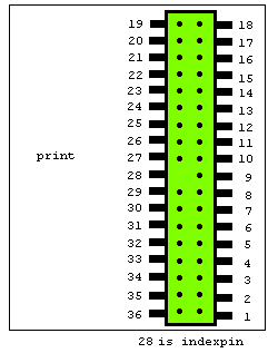
De aansluiting van een decoder volgens FX35 ziet er als volgt uit:
|
| Afbeelding: 01
|
| De connector volgens F35
|
| Tekening gemaakt door: Fred Eikelboom
|
De decoder is tegen verkeerd-om insteken beveiligd. Hiervoor dient pin 28 (zie afbeelding 01).
35-polige connector
Bij de FX35-connector is de pinbezetting als volgt uitgevoerd:
| Pen
|
Omschrijving
|
| 1 |
Motor +
|
| 2 |
Motor +
|
| 3 |
GPIO_A
|
| 4 |
GPIO_B
|
| 5 |
GPIO_C
|
| 6 |
GPIO_D
|
| 7 |
Cap +
|
| 8 |
GPIO_E
|
| 9 |
GND (massa na gelijkrichter)
|
| 10 |
Vcc (+3,3/+5,5V)
|
| 11 |
GPIO_F
|
| 12 |
1 draads bus
|
| 13 |
LS1-A
|
| 14 |
LS1-B
|
| 15 |
LS2-A
|
| 16 |
LS2-B
|
| 17 |
Motor -
|
| 18 |
Motor -
|
| 19 |
Aansluiting linker spoorstaaf (via linker wielen).
|
| 20 |
Aansluiting linker spoorstaaf (via linker wielen).
|
| 21 |
F0_f (verlichting front)
|
| 22 |
AUX10
|
| 23 |
AUX9
|
| 24 |
AUX8
|
| 25 |
AUX7
|
| 26 |
AUX6
|
| 27 |
U + (na gelijkrichter)
|
| 28 |
Indexpin (Omdraaibeveiliging)
|
| 29 |
AUX5
|
| 30 |
AUX4
|
| 31 |
AUX3
|
| 32 |
AUX2
|
| 33 |
AUX1
|
| 34 |
F0_r (verlichting achter)
|
| 35 |
Aansluiting rechter spoorstaaf (via rechter wielen).
|
| 36 |
Aansluiting rechter spoorstaaf (via rechter wielen).
Bij Drierail is dit de aansluiting van de spoorstaaf waarop de sleper rust.
|
|
|
| Tabel: 01
|
| Tabel gemaakt door: Fred Eikelboom
|
Gegevens van tabel 01 onder voorbehoud.
De afmetingen van de FX35 decoder zijn: 19,5 mm lang, 8,4 mm breed en 2,6 mm dik.
De connector-pins 1 + 2 (Motor +) staan parallel en mogen samen max. 1 ampère stroom voeren. De connector-pins 17 + 18 (Motor -) idem.
De connector-pins 19 + 20 (Stroomafname links) staan parallel en mogen samen max. 1 ampère stroom voeren.
De connector-pins 35 + 36 (Stroomafname rechts) idem.
De connector-pins 1 t/m 36 mogen max. 0,5 ampère stroom voeren.
De afmetingen van de FX35 decoder zijn: 23 mm lang, 15,5 mm breed en 6,5 mm dik.
De GPIO-aansluitingen kunnen als "ingang" of "uitgang" worden ingesteld.
Let op
Een aantal Aux-aansluitingen is niet versterkt (zie tabel 3.2 in documentatie), daar moet dus een versterker (transistor) achter!
Zie voor aanvullende informatie de documentatie hieronder.
Meer informatie
Encyclopedie:
|
|
|
|
|
|
|
Oplossingen voor rijrichtingproblemen.
|
|
|
|
|
|
|
Decoderinbouw.
|
|
|
|
|
Laatste wijziging: 17 apr 2024 11:37 (CET)
|
